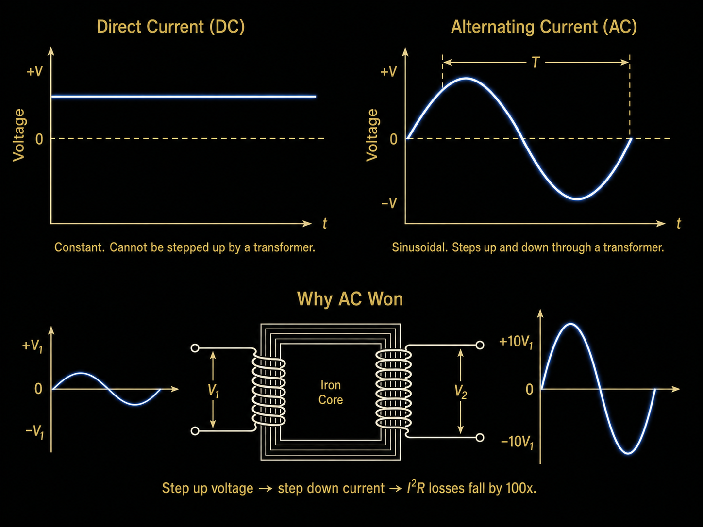
Direct current goes one way. Alternating current reverses. One of those sentences is more complicated than it sounds.
In Chapter 1 you learned what electricity is: electrons moving through a conductor, pushed by voltage, slowed by resistance, with the relationship between them described by Ohm's Law. You also learned Faraday's two rules: an electric current creates a magnetic field, and a changing magnetic field creates an electric current.
Now we need to talk about the two fundamentally different patterns of electron flow. Not the electrons themselves — those you already understand. The pattern. Because the entire story of Nikola Tesla, and the entire reason his work mattered, comes down to the difference between two patterns of current flow called DC and AC.
One of them is simple. The other turned out to be the key to the modern electric world.
Start with what is easy. Direct current, or DC, is electrons flowing in one direction, continuously. The word "direct" means exactly what it says: the flow goes directly from one place to another, without reversing.
Think back to the water-pipe analogy from Chapter 1. Voltage was the pressure difference between two points. Current was the flow rate — how many electrons (or liters of water) passed a given point per second. In that analogy, DC is simply water flowing steadily in one direction down the pipe. No turbulence. No reversal. Water enters at one end, exits at the other.
A battery produces DC. Here is why. A battery has two terminals: a positive terminal and a negative terminal. The chemistry inside the battery maintains a constant charge imbalance between them. The positive terminal is always short of electrons; the negative terminal always has a surplus. Because electrons are attracted to positive charge and repelled by negative charge, they will always flow in the same direction: from the negative terminal, through whatever circuit you have connected, to the positive terminal. As long as the battery has charge remaining, that direction never changes.
That is the whole story for DC. The electrons march steadily in one direction. The voltage is constant. The current is constant (assuming the load doesn't change). The graph of voltage versus time is a flat horizontal line.
Now for the one that is more complicated than it sounds.
Alternating current, or AC, is a current that reverses direction repeatedly. The electrons in the wire do not flow steadily from A to B. Instead, they push a little toward B, then pull back toward A, then push again, then pull back — over and over, many times per second.
At this point most people form a mental picture that is almost right, but leads them wrong. They imagine the electrons themselves sloshing back and forth along the wire like water in a bathtub, traveling significant distances in each direction. That picture is incorrect, and it will confuse you later when you try to understand why AC can transmit power over long distances at all.
Here is the correct picture. The electrons in a wire carrying AC move an almost negligibly small distance in each direction — typically less than a millimeter, even in a household wire. What travels the length of the wire is not the electrons themselves. It is the push. It is the energy.
The best analogy for this is Newton's cradle — the desk toy with five steel balls hanging in a row. When you pull the ball on one end back and release it, it swings forward, strikes the row, and the ball on the far end flies out. The balls in the middle barely move at all. Yet the energy travels from one end to the other almost instantaneously. The energy does not need the individual balls to travel the full distance. The signal travels through the chain of interactions.
AC works the same way. The electrons in the wire are packed close together. When the generator pushes electrons at one end of the wire, that push propagates through the wire almost at the speed of light, transmitted from electron to electron. The energy arrives at the light bulb (or the motor, or the toaster) without any individual electron having traveled more than a fraction of a millimeter. What alternates — what reverses — is the direction of the push, not a long-distance march of electrons.
This distinction matters. AC is about the pattern of pushing. Not about individual electron travel.
Now you need to know where AC comes from. Not from a battery — batteries produce DC. AC comes from generators. And here is the crucial fact that the entire chapter builds toward: generators naturally produce AC. They do not need to be designed to produce it. It falls out of the physics automatically.
To understand why, recall Faraday's second rule from Chapter 1: a changing magnetic field creates an electric current. The word "changing" is doing all the work. A steady magnetic field, sitting still, produces no current. The field has to change — grow, shrink, or change direction — for current to flow.
Now picture a simple generator. At its most basic, it is a coil of wire rotating inside a magnetic field. There is a permanent magnet with a north pole on one side and a south pole on the other, and between those two poles, a rectangular loop of wire that spins on an axle. When something turns that axle — a steam turbine, a water wheel, a diesel engine — the loop rotates through the magnetic field. And as it rotates, the magnetic field passing through the loop changes constantly. By Faraday's second rule, that changing field drives a current in the coil.
Walk through four positions of one full rotation:
The coil is oriented so its flat face is parallel to the magnetic field lines. The two long sides of the wire loop are cutting straight across the field lines at the maximum possible angle. Faraday's rule says the rate of change is what matters — and here, the rate of change is at its peak. The result is maximum current flowing in one direction. Call this the positive peak.
The coil has rotated 90 degrees. Now the flat face of the loop is perpendicular to the field lines — the field is passing straight through the loop face-on, not cutting across it at all. The field through the loop is at its maximum value, but it is momentarily not changing. A field that is not changing produces no current. Current drops to zero.
The coil has completed half a rotation. It is parallel to the field again — back to the geometry of position 1 — but now it is upside down. The side of the wire loop that was previously cutting through the field in the upward direction is now cutting in the downward direction. By Faraday's rule, this reverses the direction of the induced current. Maximum current flows again, but now in the opposite direction. This is the negative peak.
Another 90 degrees of rotation. The coil is perpendicular again, field is threading through it face-on, rate of change is zero. Current drops back to zero.
Then the coil completes its rotation back to 12 o'clock and the whole cycle repeats.
Plot those four values over time — positive maximum, zero, negative maximum, zero — and you get a smooth curve that rises, falls through zero, drops to a negative peak, returns through zero, and rises again. You get a sine wave. Not because anyone designed it that way. Not because a sine wave was chosen as a good waveform for electricity. A sine wave is what you get from rotation, automatically, because of the geometry of circles. The relationship between rotation and the sine function is not physics — it is trigonometry. When something spins at a constant speed, its projection onto a straight line traces a perfect sine wave.
If generators naturally produce AC, how did Edison power his DC electrical systems? He used generators too. What was the difference?
The answer is a device called a commutator: a mechanical switch built into the generator that converts the naturally alternating output into something flowing in one direction.
Here is how it works. The coil of wire rotates, as before. But instead of connecting the two ends of the coil to fixed output contacts, the commutator connects them through a split ring — a ring that has been cut in half, with the two halves electrically insulated from each other. Each half of the split ring is connected to one end of the coil. Two stationary brushes (usually carbon) press against the outside of the spinning ring.
As the coil rotates, the split ring rotates with it. Every half turn — precisely when the current in the coil would naturally reverse — the two halves of the ring swap which brush they are touching. The output that was connected to the left brush is now connected to the right brush, and vice versa. The reversal in the coil is exactly cancelled by the reversal in the connections. The result at the output terminals is always the same polarity: positive stays positive, negative stays negative.
The output is not perfectly smooth — it pulses rather than being a flat line, because you are still following the underlying sine wave, just flipping the negative halves upward to join the positive halves. The waveform looks like a series of humps all pointing the same direction. In real DC generators, multiple coil segments and commutator segments are used to smooth these humps into something close to a flat line.
It is worth pausing to describe these two waveforms precisely, because we will refer to them throughout the rest of the book.
AC is a smooth sine wave that oscillates above and below a center line of zero. It rises to a positive peak, sweeps back through zero, drops to a negative peak of equal magnitude, returns through zero, and repeats. The center line — zero — represents no net current flow. Voltage and current both follow this pattern in sync (in a purely resistive circuit, at least).
DC is a flat horizontal line. Voltage is constant. Current is constant. Nothing oscillates.
Here is a subtlety about AC that trips people up, and it is worth getting right now because the number on your wall outlet depends on it.
Your wall outlet in the United States is rated at 120 volts. But 120 volts is not the highest voltage in the sine wave. The sine wave swings higher than that — and lower, in the negative direction. So what does "120 volts" actually mean?
It means the RMS voltage is 120 volts. RMS stands for Root Mean Square. It sounds like a mathematical procedure (because it is one), but the practical meaning is simple: the RMS voltage of an AC waveform is the equivalent DC voltage that would do the same amount of heating work in a resistor.
If you replaced your AC outlet with a DC source, and you wanted that DC source to heat your toaster at exactly the same rate as the AC does, you would set it to 120 volts DC. That is what 120 V RMS means. It is the "effective" voltage — the AC voltage stated in terms of its real-world heating and working power.
The actual peak of the sine wave is higher. For a 60 Hz, 120 V RMS outlet, the peak voltage is:
V_peak = V_RMS × √2 ≈ 120 × 1.414 ≈ 170 voltsThe relationship works in both directions. If you measure the peak and want the RMS:
V_RMS = V_peak × (1/√2) ≈ V_peak × 0.707So the sine wave at your outlet swings from +170 V to −170 V, sixty times per second. It passes through zero 120 times per second. The number "120 V" that is stamped on your outlet and on your appliances is the RMS value — not the peak.
Why does this matter? For two reasons. First, your electrical insulation has to be rated for the peak, not the RMS — the wire insulation on a 120V circuit has to survive 170V transients. Second, whenever you see a voltage rating on AC equipment, you need to know it refers to RMS unless the label explicitly says "peak."
One more property of AC needs to be pinned down before we can move on: frequency.
Frequency is how many complete back-and-forth cycles happen per second. One complete cycle means: start at zero, rise to positive peak, return through zero, drop to negative peak, return to zero again. That is one cycle.
The unit of frequency is the hertz, abbreviated Hz, named after Heinrich Hertz, the physicist who first demonstrated radio waves. One hertz means one complete cycle per second.
1 Hz = 1 cycle per secondThe United States and Canada use 60 Hz AC. Most of Europe, Asia, and Africa use 50 Hz. At 60 Hz, the current completes 60 full cycles per second, which means it reverses direction 120 times per second.
Think about a ceiling fan. On low speed, it completes perhaps one rotation per second — roughly 1 Hz of mechanical rotation. On high speed, maybe three rotations per second — 3 Hz. A generator works the same way: the faster you spin it, the higher the frequency of the AC it produces. US power plants run their generators at precisely 3,600 RPM to produce exactly 60 Hz. (3,600 rotations per minute ÷ 60 seconds per minute = 60 rotations per second = 60 Hz.)
The period of one cycle — the time it takes to complete one full back-and-forth — is the reciprocal of the frequency:
Period = 1 / FrequencyAt 60 Hz: period = 1/60 second ≈ 16.7 milliseconds per cycle.
At 50 Hz: period = 1/50 second = 20 milliseconds per cycle.
You will need these numbers in Experiment 2.1 below, when you measure the period directly on an oscilloscope.
The period (16.7 milliseconds at 60 Hz) is a time measurement — how long one cycle takes. You can feel this when you accidentally touch a live wire: 60 direction-reversals per second, your muscles responding in time.
The wavelength is completely different: it is the physical distance in space between two peaks. Electromagnetic waves travel at the speed of light (300,000 km/s). In the 1/60 second between peaks, light travels:
300,000 km/s × (1/60) s = 5,000 km
That is the wavelength of 60 Hz AC — not 5,000 km of time, but 5,000 km of space. The peaks are 5,000 km apart in the real world. The wavelength is enormous not because the frequency is low, but because the wave travels at the speed of light.
This matters because power lines (even the longest ones, ~2,000 km) are shorter than one wavelength. Engineers call this "electrically short," which means simple Ohm's Law applies and you do not need to worry about wave effects. At radio frequencies, wavelengths shrink to meters or centimeters — then wave effects become unavoidable, and the engineering gets harder. More on this when we reach the radio chapter.
The 50 Hz vs. 60 Hz difference is historical, not technical. Both work fine. The US standardized on 60 Hz in the 1890s largely due to choices made during the early buildout of the AC grid — choices made partly by Tesla's partner George Westinghouse, partly by early equipment manufacturers. Europe went its own way with 50 Hz. By the time anyone had the standing to impose a global standard, both systems were too deeply entrenched to change.
There is no engineering reason to prefer one over the other for basic power distribution. Modern equipment — including virtually every laptop charger and phone charger sold today — operates on either frequency without any adjustment needed. The label on your charger brick that reads "100-240V ~ 50/60Hz" is telling you exactly that.
Before we go further, a digression that is not really a digression. Lightning matters to the Tesla story — and the physics of lightning is a good exercise in applying everything this chapter has covered so far.
Lightning is predominantly DC. It is a unidirectional discharge of electrical charge that has built up between a cloud and the ground (or between two clouds). The charge built up over time, in one polarity, and then discharges in one direction. There is no oscillating generator producing it. The main stroke is a single-direction pulse, not a back-and-forth alternation.
The typical main lightning stroke lasts roughly 200 microseconds — two ten-thousandths of a second. In that brief window, peak currents of 20,000 to 30,000 amperes are common; large strikes have been measured above 300,000 amperes. For comparison, a standard household circuit breaker trips at 15 or 20 amperes. A lightning strike carries 1,000 to 15,000 times as much current, for a fraction of a millisecond.
However — and this is where it gets interesting — after the main DC stroke, the energy does not simply stop. The channel of ionized air rings like a bell that has been struck. The current oscillates back and forth at high frequency, decaying rapidly, for a few hundred microseconds after the main event. This oscillatory "ringing" is not the main event; it is an artifact of the inductance and capacitance of the discharge channel. But it is AC-like behavior, superimposed on what is fundamentally a DC discharge.
Why does this matter for understanding Tesla? Because Tesla was fascinated by the physics of the lightning stroke — specifically that enormous current delivered in an extremely short time, the sharp leading edge of the pulse. His high-voltage impulse work, developed in the 1890s, was an attempt to create and control discharges that mimicked what nature does in that 200-microsecond window. The distinction between a smooth, slow sine wave at 60 Hz and a violent, brief impulse was central to his later research program. Both are electricity. They are not the same phenomenon at all.
Lightning rods work by providing a low-resistance path from the top of a structure to the ground. When charge is discharged through the rod, it travels through copper (very low resistance) rather than through wood, stone, or human beings (much higher resistance). The energy dissipates in the earth.
Surge protectors work on a related principle. The component inside a surge protector that actually does the work is a Metal Oxide Varistor, or MOV. Under normal voltage, it has very high resistance and lets current pass through to your equipment. When a spike arrives — a nearby lightning strike inducing a transient on the power line — the MOV's resistance drops suddenly and it diverts the excess energy to ground before it reaches your electronics. A surge protector that has absorbed one large lightning transient may be dead afterward, even if its indicator light is still on. Replace them after any significant nearby strike.
You may have noticed that a 12V car battery doesn't arc when you bring a wire near its terminals, but a high-voltage line can throw a visible spark across a significant gap. This is not an accident. It is a fundamental property of how electricity breaks through air.
Air is an insulator — until the electric field across it exceeds about 3 million volts per meter (3,000 volts per millimeter). When the field exceeds that threshold, electrons are ripped off air molecules, creating a conductive plasma channel. That is an arc. The minimum gap that a given voltage can jump is:
gap (meters) = voltage / 3,000,000
At 12V, that gap is 4 micrometers — essentially zero. Wires would have to be touching. At 120V it is 40 micrometers, still barely visible. At 10,000V you get 3mm. At 100,000V (the range of Tesla coil outputs) you get 33mm — over an inch of visible arc reaching through open air. Lightning, at 100 million volts or more, ionizes a column of air across kilometers.
Static electricity — the shock from a carpet — is typically 10,000–30,000 volts, sometimes higher in dry conditions. The current is measured in milliamps for a fraction of a millisecond. Extremely high voltage, essentially no current. That enormous voltage is what ionizes the tiny gap at your fingertip. The negligible current is why it hurts but doesn't kill you.
Arc welders seem like an exception — they arc visibly. But here is the surprise: a typical stick welder runs at only 20–80 volts. That is far too low to jump even 1mm of fresh air on its own. What actually happens is that you touch the electrode to the metal first, creating a short circuit. The enormous current (100–300 amperes) instantly heats the contact point to plasma temperature. When you pull the electrode back, that plasma is already conductive — and plasma sustains an arc at much lower voltage than it takes to start one in fresh air. Once the arc is burning, it self-sustains at 20–30V across the gap. The high current does the welding; the high voltage is not what you need.
The Tesla coil works the opposite way: genuinely high voltage (tens of thousands to millions of volts) ionizes fresh air directly, with no touching required. That is why its sparks branch and reach outward through open space, while a welder requires contact to start. Both are arcs. The physics is the same. The path to get there is different.
There is one more property of AC that is worth understanding now, partly because it is real physics, and partly because it has been used to sell a great deal of expensive cable that offers no measurable benefit.
In a DC circuit, current distributes itself evenly across the full cross-section of the conductor. Picture water filling a pipe uniformly from wall to wall. In an AC circuit, the situation is different: current tends to flow near the surface of the conductor, with less current in the interior. This is called the skin effect.
Why does this happen? It is a consequence of inductance. The interior of a conductor experiences more electromagnetic "opposition" to changing current than the surface does, because the changing magnetic field from the current itself acts to oppose changes in current (Faraday's law again). At high frequencies, where current is changing direction rapidly, this opposition becomes significant, and current is effectively pushed toward the surface.
The depth at which the current density drops to about 37% of its surface value is called the skin depth. Skin depth gets smaller as frequency rises. The formula involves the material's conductivity and permeability, but the numbers for copper tell the practical story:
| Frequency | Skin Depth in Copper | Practical Meaning |
|---|---|---|
| 60 Hz (US power grid) | ~8.5 mm | Essentially no effect — most copper conductors are smaller than 8.5 mm radius |
| 1 kHz (low audio) | ~2.1 mm | Still negligible for typical wire gauges |
| 20 kHz (top of audio range) | ~0.47 mm | Small effect in very thick conductors; irrelevant in 12–18 AWG speaker wire |
| 1 MHz (AM radio) | ~0.066 mm | Significant; RF cables need to be designed for it |
At 60 Hz, the skin depth in copper is about 8.5 millimeters. The radius of even a heavy 0 AWG power cable is about 4 mm. So for power distribution at 60 Hz, the conductor is smaller than the skin depth, which means the current fills essentially the full cross-section. The skin effect is irrelevant.
At audio frequencies — say, the highest notes a speaker can reproduce at 20 kHz — the skin depth in copper is 0.47 mm. That is less than half a millimeter. Standard 12-gauge speaker wire has a radius of about 1.03 mm. So at the very top of the audio range, in very thick wire, current would be concentrated in the outer half-millimeter or so. In practice, the measured difference in resistance between standard 12-gauge copper speaker wire and exotic multi-strand "audiophile" cable at home-audio frequencies and distances under 10 feet is below the threshold of measurement with ordinary test equipment.
The practical rule: use 12-gauge copper for speaker runs under 8 meters. If your run is longer, go to 10-gauge. Stop there. The $500 cable with individually insulated strands and oxygen-free copper is real physics applied to produce an unmeasurable improvement at home-audio scales. The skin effect is genuine. The marketing based on it is not.
At radio frequencies — megahertz and above — the skin effect matters enormously and determines how RF cables and antennas are designed. That becomes relevant when we reach Tesla's radio frequency work in Chapter 9.
The skin effect taken to its logical extreme produces one of the most dramatic demonstrations in science education: the Faraday cage.
At the Museum of Science in Boston's Theater of Electricity, the world's largest air-insulated Van de Graaff generator — 30 feet tall, built by Robert Van de Graaff at MIT in 1931 and capable of generating 2.5 million volts — fires enormous electrical discharges while a person stands calmly inside a metal cage. The discharges crawl across the outside of the cage in brilliant arcing streamers. The person inside is completely unharmed.
The reason: a metal enclosure distributes any electric charge on its outer surface. The interior has no electric field. The discharge has no reason to go inside — the metal cage surface is a far easier path than the air inside. The same principle is why microwave ovens have a metal mesh on the door (the microwaves can't get out), why elevator cabs block cell phone signals, and why shielded cables prevent interference in audio equipment.
Michael Faraday demonstrated this in 1836 by lining a room with metal foil and sitting inside it while massive electrical charges were applied to the outside. He could detect no effect within the room. The cage bears his name.
This is also partly why the skin effect matters: at the high frequencies produced by a Tesla coil, the skin depth is tiny — a fraction of a millimeter. All of the electrical energy stays on the surface of any conductor it encounters. If that conductor is a metal cage around a person, the energy never reaches the person. Chapter 10 covers Tesla coils in detail, including exactly what those streamers are and why they branch the way they do.
Answers: (1) 340 × 0.707 ≈ 240 V RMS — this is the European standard outlet voltage, and that is not a coincidence. (2) No — the skin depth is more than six times the cable's radius, so current fills the full cross-section.
The difference between AC and DC is not abstract — it is directly visible if you have the right instrument. This experiment uses an oscilloscope to display the waveform from a battery (DC) and from a small AC transformer, so you can see the flat line and the sine wave side by side.
Use only the low-voltage output side of the transformer — the output terminals, not the wall plug. Never connect an oscilloscope probe to a standard wall outlet. The transformer steps the voltage down to safe levels; that is why it is in this experiment.
The flat line is the signature of a constant-direction push. The sine wave is the signature of rotation — the same rotation we traced through four positions in Section 3. The shape on screen is not an abstraction. It is the geometry of a spinning coil, made visible.
From Chapter 1 you know that resistance consumes voltage. Every wire has resistance. A long wire has more resistance than a short wire. This experiment makes Edison's central distribution problem tangible by measuring how much voltage is lost in a simulated long wire run.
Connect the 9V battery to one end of the 100-foot wire run (50 feet out, 50 feet back). Connect the 10Ω resistor at the far end, across the two wire ends. You now have a circuit where current must travel 50 feet out and 50 feet back to reach the load — 100 feet of wire total in the circuit path.
24-AWG copper wire has a resistance of approximately 84.2 milliohms per foot, or about 0.0842 Ω/ft. For 100 feet (50 out + 50 return):
Wire resistance = 100 ft × 0.0842 Ω/ft ≈ 8.4 ΩYou now have a voltage divider: 8.4Ω of wire resistance in series with a 10Ω load. The fraction of the total voltage that reaches the load:
Voltage fraction at load = 10 / (10 + 8.4) = 10 / 18.4 ≈ 0.54So roughly 54% of the supply voltage reaches the load. The other 46% is wasted heating the wire.
| Wire Gauge | Wire Resistance (100 ft) | Voltage at Load | Percentage Lost in Wire |
|---|---|---|---|
| 24 AWG | ~8.4 Ω | ~4.9 V (from 9V) | ~46% |
| 18 AWG | ~2.1 Ω | ~7.5 V (from 9V) | ~17% |
Edison's DC distribution system in Manhattan in the 1880s operated at roughly 110 volts. His generators were located at the Pearl Street Station. A customer half a mile from the station received noticeably dimmer light than a customer next door to it — the wire resistance between the station and the distant customer consumed a significant fraction of the voltage before it arrived.
There was no elegant solution to this problem in a DC system. You could use thicker wire (expensive and heavy), build more generating stations closer to customers (very expensive), or raise the voltage (which made everything in the customer's home more dangerous). Edison pursued all three in various combinations, with limited success.
The solution to this problem — the reason it is not your problem today — requires a device called a transformer, which only works with AC. That is Chapter 6. But you need to feel the problem first before the solution will mean anything.
You built, in miniature, the central problem of 19th-century electrical distribution. The 46% loss in the 24-AWG wire is not a flaw in your experiment. It is the physics that forced the entire structure of the modern electrical grid into existence.